
eManual
19039-Machine for automatic assembly of White Pole

3.1 Description of controls
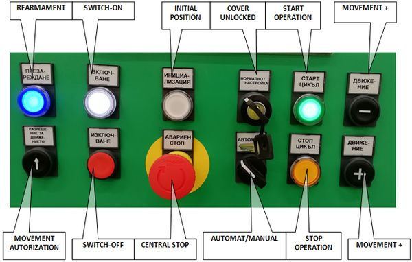

Illuminated pushbutton ”SWITCH-ON“
It is used for machine switching-on. Its depression results in connection of electric power supply to power elements.
Readiness of the machine to switch on power circuits is indicated by flashing of the pushbutton. Once the power circuits are switched on, the pushbutton remains alight.
Illuminated pushbutton ”REARMAMENT“
Upon pushing the button, the main air valve is opened and the machine is aerated.
Provided the machine is ready to be aerated, the pushbutton is flashing. Once the machine is aerated, the pushbutton remains alight.
ATTENTION: Machine switching-on is possible only if all cover doors are closed and switches CENTRAL STOP are released.
!!! ATTENTION !!!
Before machine switching-on it is necessary to check equipment condition and possibly to remove the parts and other objects that could cause a collision.
Pushbutton ”MACHINE SWITCH-OFF“
It is used for machine switching-off. After its depression, power elements are disconnected from electric power supply and closing of the main air valve. Only control system remains alive. Execute switching-off only if the equipment does not work in automatic mode any more. If the equipment is switched off during operation, before equipment restart always check working space of the machine.
Illuminated pushbutton „SWITCH-ON OPERATION“
It is used for switching-on of automatic operation of the equipment if all necessary conditions are fulfilled.
The equipment readiness for automatic operation start-up is indicated by means of information message on the main screen of automatic operation ”Stop“ and flashing of the pushbutton.
Automatic mode is indicated with constant light of the pushbutton.
Pushbutton ”SWITCH-OFF OPERATION“
It is used for termination of automatic operation of the equipment.
Its depression results in termination of operations on the parts in progress.
Switch “AUT/MAN“
It is used for machine mode selection – automatic mode/manual mode
In MAN position it is possible to control (switch on/off) particular functional units of the equipment. The selection of a controlled unit and control is executed by means of interactive pane.
In AUT position, the equipment is ready for operation in normal automatic cycle.
Provided the key is switched to MAN position in the automatic mode, the machine is stopped automatically.
Switch “COVER UNLOCK“
Switching-over of the key to COVER UNLOCK position results in unlocking of safety switches of the cover. The door cover opening is enabled only after this unlocking. Covers are unlocked only if the automatic mode is switched off.
In UNLOCK position the function of safety cover switches is disabled. This is necessary e.g. for the machine check and adjustment. The operating company is obliged to define authorized persons who can use this key switch. The covers may only be disabled by an authorized and fully trained person. This person working on the equipment with disabled function of safety covers shall execute the work very cautiously. After termination of the work before leaving the workplace, the machine shall be restored to original condition when all covers are closed, the cover locking cancelled and control key removed from the controller. The staff disabling safety covers is obliged to prevent an access of other persons to working space of the machine.
Illuminated pushbutton ”INITIAL POSITION“
It is used for set-up of the whole machine to initial position in manual or automatic mode if assembly cycle is not just in process.
Signal lamp indicates machine set-up to initial position; if the signal light is lighting, the equipment is completely ready for operation in automatic mode.
Necessary initialization of the machine is indicated with flashing of the pushbutton.
Pushbutton “MOVEMENT AUTHORIZATION”
It is used for authorization of the unit movement in manual mode and opened covers of the machine.
Pushbutton “MOVEMENT +”
Pushbutton indicating motion forward in manual mode. It moves the chosen unit into working position.
It functions in combination with “MOVEMENT AUTHORIZATION” pushbutton only.
Pushbutton “MOVEMENT -”
Pushbutton indicating motion backward in manual mode. It moves the chosen unit into initial position.
It functions in combination with “MOVEMENT AUTHORIZATION” pushbutton only.
5.5 ST22:Change Over COVER
The Changeover COVER process can be activated manually from the control panel. Automatically, the device is required when the type of COVER components present in the left or right ST22 stack does not match the required COVER to process the assembly to ST22.
Step 1: Check/edit information about cover type in bowls and confirm
Step2: Check/edit information about used bowl selection L/R and confirm
Step 3: Open Cover over conveyor of ST22 and confirm

Step 4: Open evacuation gate on the end of selected conveyor and confirm

Step 5: Open evacuation gate on the selected hopper and confirm
Step 6: Insert box bellow selected hopper and confirm
Step 7: Insert box bellow return chute between hoppers of ST22 and confirm
Step 8: Open evacuation gate of return chute between hoppers of ST22 and confirm
Step 9: Push button "Start conveyor" for empting of feeding system of Cover

Step 10: Validate empty selected hopper and confirm
Step 11: Validate empty selected bowl and confirm
Step 12: Validate empty selected belt conveyor and confirm
Step 13: Empty box for NOK Covers from ST22 and Confirm
Step 14: Close evacuation gate of return chute between hoppers of ST22 and confirm
Step 15: Close evacuation gate on the selected hopper and confirm
Step 16: Close evacuation gate on the end of selected conveyor and confirm
Step 17: Insert new type of Cover to selected hopper and Confirm
Step 18: Waiting for fulfilment of conveyor
7.8 ST10: Insertion of Toggle
Description of the function and adjustment

The working station ST10 performs:
-
Delivery of the TOGGLE to the taking place.
-
Transfer of the TOGGLE into the preparatory nest including setting of the TOGGLE orientation in one position
Transfer of the TOGGLE by means of the handling unit from the preparatory nest to the body of the CASE in the nest on the turntable.
Important information on the function of the working node ST10:

Cycling unit V10_04 + V10_05
In the initial position it is set up above the preparatory place with a stop.
The TOGGLE is transferred into the rotary nest only if the following conditions are fulfilled:
-
minimum stock of TOGGLE B0.6.44=1
-
TOGGLE presence registered in the position on the stop of the clock system B0.6.45=1
-
no part is present in the rotary nest after TOGGLE turning over (memory information)
Rotary unit V10_06 + V10_13
At the beginning of the automatic cycle the rotary nest is oriented so as to enable transfer of the TOGGLE from the vibrating tray into the rotary nest – V10_06 in intermediate position, V10_13 in initial position IP.
The unit V10_06 is set in intermediate position, where it has not active sensor of neither IP nor WP, by means of V10_13.
If V10_13 is set in initial position IP, the rotary unit V10_06 is in intermediate position.
After the move of the unit V10_13 to the working position WP, it is possible to move the unit V10_06 to end positions IP/WP, which enable transfer of TOGGLE onto the auxiliary turnover nest.
The unit V10_13 has only sensor of IP, which is installed on the rotary unit V10_06.
Before transfer itself the TOGGLE orientation is detected by means of the sensor B0.6.46. According to this orientation memory the rotary nest V10_06 is subsequently turned to initial or working position.
a. If the sensor B0.6.46=1, the unit V10_06 is turned to the initial position IP.
b. If the sensor B0.6.46=0, the unit V10_06 is turned to the working position WP.
Unit V10_7
In the initial position, it is retracted from the rotary nest. By movement to the working position, it performs the TOGGLE withdrawal from the rotary head and putting onto the centre of the turnover nest, which at this time must be lifted to the vertical position.
Unit V10_8
In the initial position the nest is set in horizontal position.
Sensor B0.6.47
– It detects presence of the TOGGLE in the turnover nest. The part is called only if the nest is in the horizontal initial position. If the TOGGLE is present, the sensor B0.6.47=1.

In the initial position the manipulator is in the upper position above the turntable. The tongs are open and turned to the position for gripping the TOGGLE from the auxiliary turnover nest V10_08.
Sensor B0.5.24
– It detects presence of TOGGLE in the CASE assembly after completion of handling and its insertion in the CASE assembly.
If the TOGGLE is present, the sensor B0.5.24=1.